Ελληνικά
Your cart
There are no more items in your cart

 Educational Products
 School Equipment
 Stationery
 STEM - Robotics - Programming
 Electronics
 Educational Toys & Construction Kits
 Tools & Adhesives
 Craft Materials
 Art Supplies
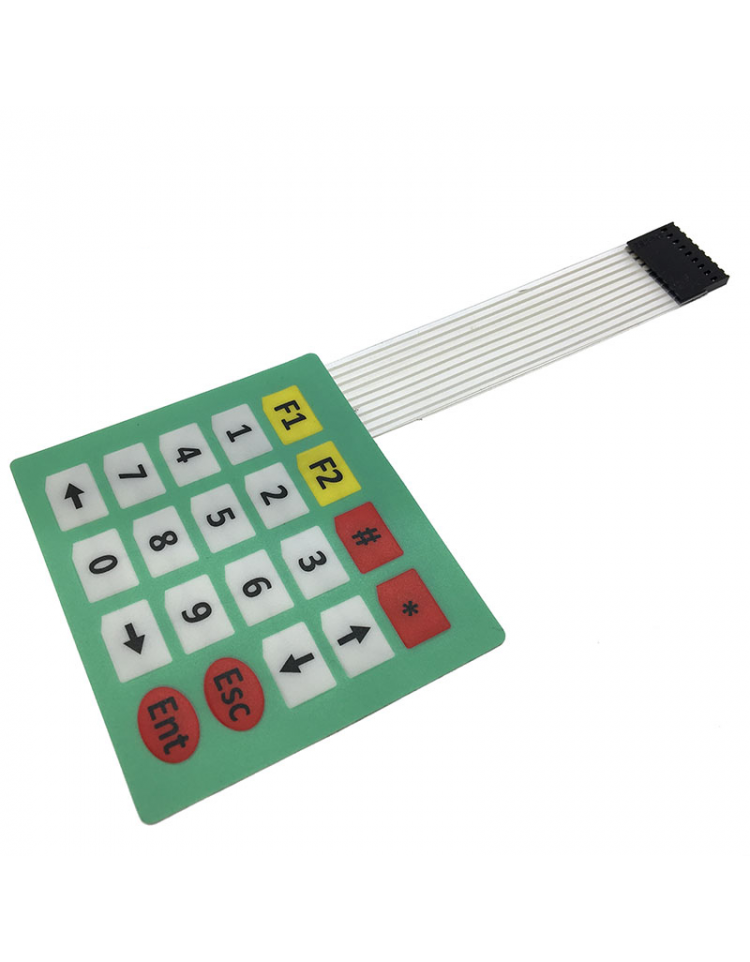
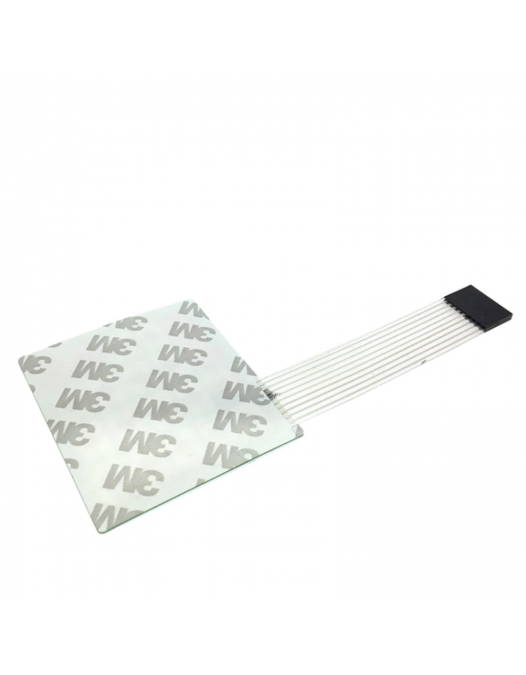
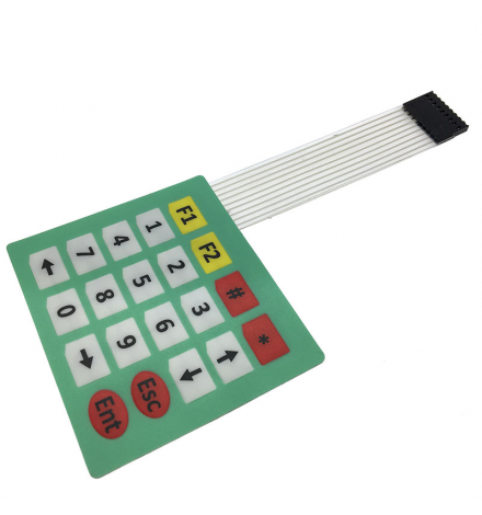
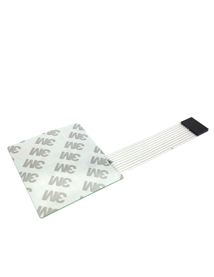
The Membrane 4×5 Matrix Keypad is a compact, ultra-thin 20-key input device designed for microcontroller projects, prototyping, and embedded systems. With its 9-pin ribbon connector and passive matrix scanning interface, it gives you full access to all 20 keys using only 9 GPIO pins — 4 rows and 5 columns. The adhesive backing lets you mount it permanently to any flat surface, making it a clean and practical addition to custom enclosures, control panels, or breadboard setups.
The 9-pin ribbon cable maps to 4 row lines and 5 column lines. The matrix scanning principle works as follows: set one row LOW at a time, then read each column pin — a LOW reading on a column indicates a pressed key at that row/column intersection.
| Pin | Symbol | Description |
|---|---|---|
| 1 | R1 | Row 1 (top row) |
| 2 | R2 | Row 2 |
| 3 | R3 | Row 3 |
| 4 | R4 | Row 4 (bottom row) |
| 5 | C1 | Column 1 (leftmost) |
| 6 | C2 | Column 2 |
| 7 | C3 | Column 3 |
| 8 | C4 | Column 4 |
| 9 | C5 | Column 5 (rightmost) |
Wiring note: Connect the 4 row pins to 4 digital output pins and the 5 column pins to 5 digital input pins (with internal pull-ups enabled) on your microcontroller. No external resistors required when using INPUT_PULLUP mode on Arduino.
| Parameter | Value |
|---|---|
| Interface | Direct GPIO Matrix Scanning (4 rows × 5 columns) |
| Number of Keys | 20 |
| Operating Voltage | 3.3V – 5V DC |
| Max Voltage (circuit) | 50V DC |
| Max Current | 100 mA |
| Contact Resistance | 0.5 – 10 Ω |
| Insulation Resistance | ≥ 100 MΩ @ 100V DC |
| Dielectric Withstand | 250V RMS (50–60 Hz, 1 min) |
| Contact Bounce | ≤ 5–6 ms |
| Operating Temperature | −20°C to +60°C |
| Storage Temperature | +15°C to +35°C |
| Storage Humidity | 70% – 90% |
| Panel Size | 75 × 85 mm |
| Cable Length | 18 cm |
| Output Connector | 9-pin ribbon cable |
| Mounting | Adhesive backing (peel-and-stick) |
Q: Do I need external pull-up or pull-down resistors for this keypad?
A: No — when using Arduino, simply configure the column pins as INPUT_PULLUP in your sketch. The internal pull-up resistors handle the logic correctly, and the Keypad.h library does this automatically.
Q: Can I use this keypad with an ESP32 or Raspberry Pi?
A: Yes. The keypad operates at 3.3V–5V, making it directly compatible with 3.3V GPIO platforms like the ESP32 and Raspberry Pi without any level-shifting circuitry.
Package Contents: 1 × Membrane 4×5 Matrix Keypad (20 keys) with 9-pin ribbon cable (18 cm) and adhesive backing pre-applied.