Ελληνικά
Your cart
There are no more items in your cart


 Educational Products
 School Equipment
 Stationery
 STEM - Robotics - Programming
 Electronics
 Educational Toys & Construction Kits
 Tools & Adhesives
 Craft Materials
 Art Supplies
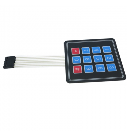
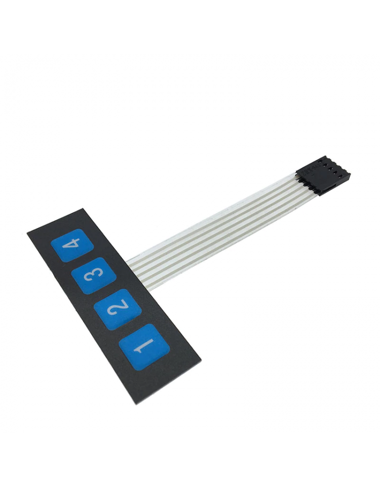
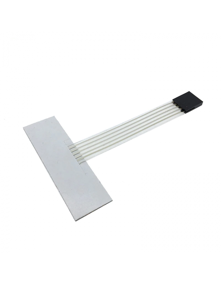
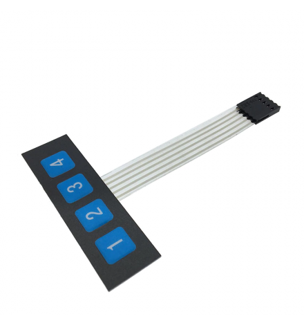
The Membrane 1×4 Matrix Keypad is a compact, flexible input device featuring 4 buttons arranged in a single row. Thanks to its ultra-thin membrane construction and self-adhesive backing, it integrates seamlessly into enclosures, panels, and DIY project housings. Each button is independently wired via a flexible printed circuit (FPC), making it extremely simple to interface with any microcontroller — no complex matrix scanning code is required. It is an ideal choice for makers, students, and engineers who need a reliable, low-profile user input solution for prototyping or finished products.
The keypad exposes 4 signal pins (one per button) via the FPC connector. Each pin corresponds directly to one key. Wiring is straightforward — connect each signal pin to a digital GPIO input on your microcontroller and enable the internal pull-up resistor (or use an external 10kΩ pull-up). Pressing a key pulls the corresponding pin LOW.
| Pin | Symbol | Description |
|---|---|---|
| 1 | K1 | Button 1 signal output — active LOW when pressed |
| 2 | K2 | Button 2 signal output — active LOW when pressed |
| 3 | K3 | Button 3 signal output — active LOW when pressed |
| 4 | K4 | Button 4 signal output — active LOW when pressed |
Wiring note: Connect each signal pin (K1–K4) to a digital input pin on your Arduino (e.g., D2–D5). Enable INPUT_PULLUP in your sketch. No common GND or VCC pin is required on the keypad itself — the buttons act as simple normally-open switches connecting the signal line to GND when pressed.
| Interface / Protocol | Direct GPIO (Digital I/O) — 4 independent signal lines |
| Operating Voltage (Logic) | 3.3V – 5V DC |
| Max Voltage per Button | 24V DC |
| Max Current per Button | 30 mA |
| Operating Temperature | 0°C to 50°C |
| Number of Keys | 4 (1×4 layout) |
| Circuit Type | FPC (Flexible Printed Circuit) |
| Pad Size | 68 × 20 mm |
| Total Length (with cable) | 107 mm |
| Mounting | Self-adhesive backing |
| MPN | N/A |
Q: Does this keypad require matrix scanning code like a 4×4 keypad?
A: No. Unlike larger matrix keypads, this 1×4 model wires each button independently to its own signal pin. You simply read 4 separate GPIO pins — no row/column scanning or Keypad library needed. This makes the code much simpler: just use digitalRead() on each pin with INPUT_PULLUP enabled.
Q: How do I mount the keypad securely?
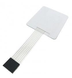
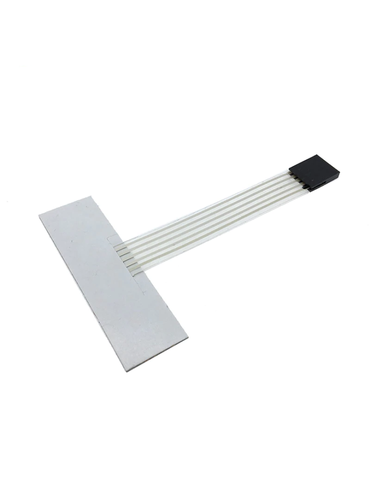
A: The keypad has a self-adhesive backing — peel off the protective paper and press firmly onto any clean, flat surface. It adheres well to plastic, metal, and acrylic panels and maintains a low profile due to its thin membrane construction.
Package Contents: 1× Membrane 1×4 Matrix Keypad with FPC cable