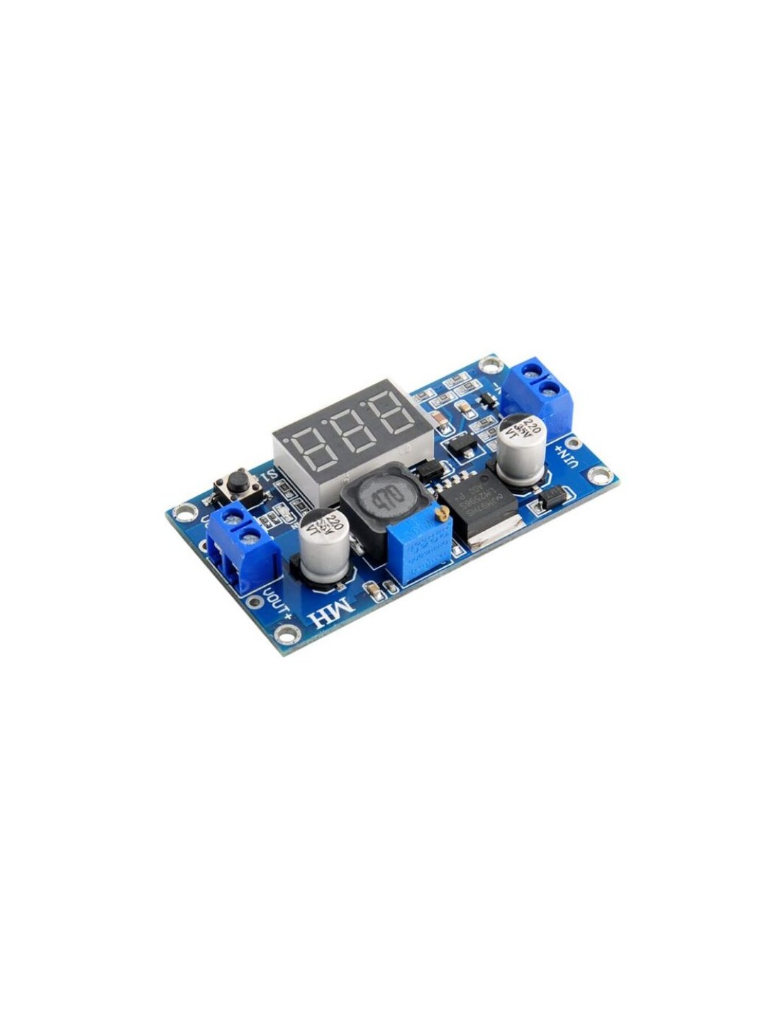
LM2596 Step-Down Buck Module with LED Display

LM2596 Step-Down Buck Module with LED Display

Modules
DET823
Part.No: ΝΑ068
€7.95
Out of Stock
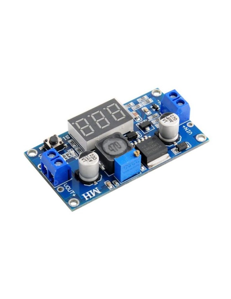
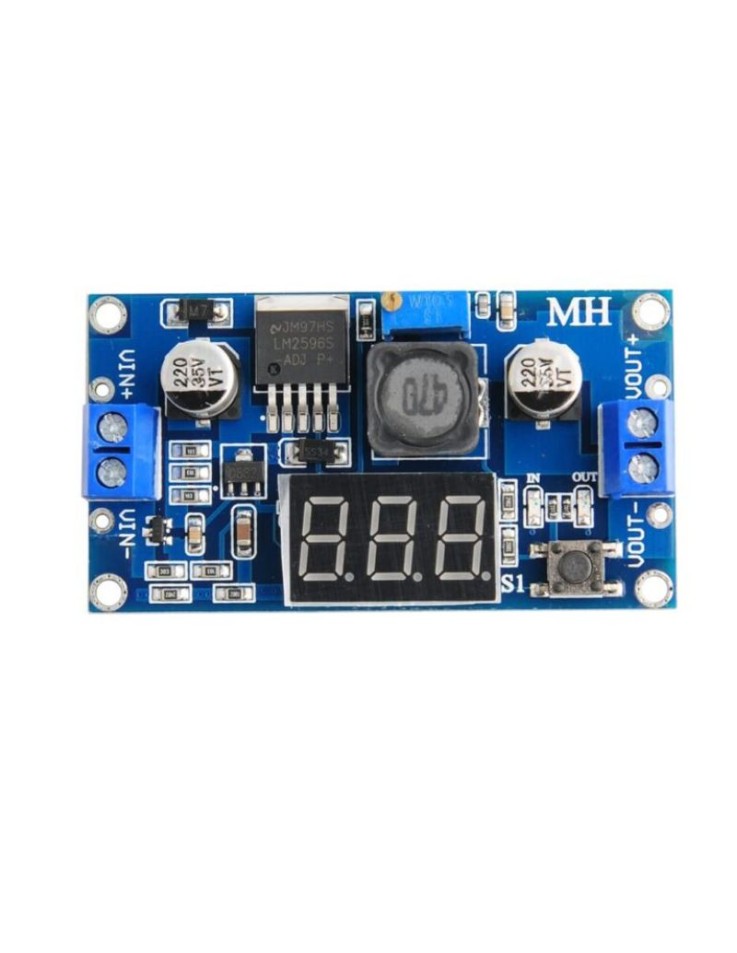
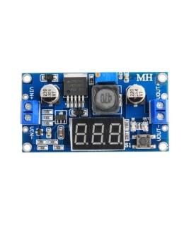
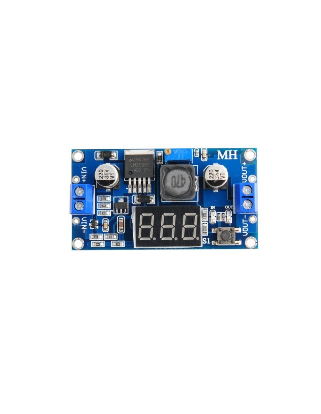
The LM2596 Step-Down Buck Module (MPN: NA068) accepts 4.0V–40V DC input and delivers an adjustable 1.25V–37V DC output. A built-in red LED display shows real-time voltage readings, making it ideal for DIY power supply projects, Arduino, and Raspberry Pi builds.


The LM2596 Step-Down (Buck) Converter Module (MPN: NA068) is a versatile, high-efficiency voltage reduction module designed for makers, engineers, and hobbyists. It accepts a wide input voltage range of 4.0V–40V DC and steps it down to a stable, adjustable output of 1.25V–37V DC — all while displaying real-time voltage values on a built-in red LED screen. Whether you need to power a 5V Arduino from a 12V car battery or regulate voltage in an IoT automation project, this module offers precision and convenience in a compact form factor.

Key Features

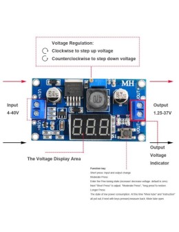
  • Wide Input Range (4.0V–40V DC): Accepts power from a broad range of sources — from USB power banks to 24V industrial supplies → maximises versatility across projects
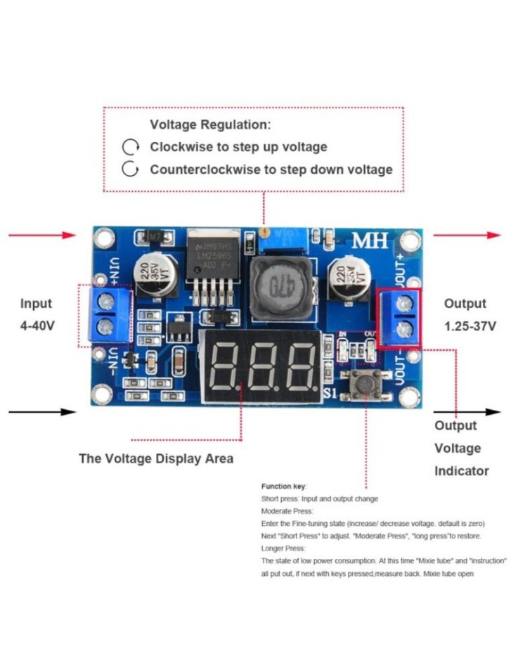
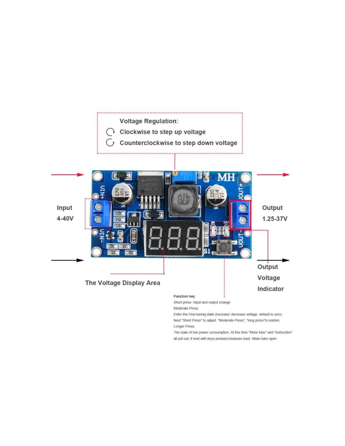
  • Adjustable Output Voltage (1.25V–37V DC): Fine-tune the output with the onboard potentiometer → powers virtually any low-voltage circuit
  • Built-in Red LED Voltmeter: Real-time digital display shows current voltage at a glance → no external multimeter needed during setup
  • Display Toggle Switch: A dedicated tactile button switches the display between input and output voltage readings → instant diagnostic capability
  • LM2596 Switching Regulator IC: Industry-standard step-down IC with built-in protection and high efficiency → less heat, more reliable operation

Pinout & Wiring

TerminalSymbolDescription
Input PositiveIN+Connect to positive terminal of DC power source (4.0V–40V)
Input NegativeIN−Connect to ground / negative terminal of power source
Output PositiveOUT+Regulated positive voltage output to your circuit
Output NegativeOUT−Ground reference for output circuit

Wiring note: Always connect IN− and OUT− to a common ground. Adjust the onboard potentiometer before connecting your load to set the correct output voltage. Use the LED display toggle button to verify both input and output readings.

Compatibility

  • Arduino UNO / Nano / Mega: Set output to 5V to power the board directly via its VIN or 5V pin from a 9V–12V source
  • Raspberry Pi (all models): Set output to exactly 5.1V for stable operation — the LM2596 output covers the 3.3V–5V range needed
  • ESP32 / ESP8266: Set output to 3.3V for direct MCU supply from higher-voltage sources such as 12V adapters
  • General Electronics / IoT: Any project requiring a stable regulated DC voltage between 1.25V and 37V

Typical Applications

  • DIY bench power supply: Use with a 12V–24V adapter to build a variable lab power supply with a built-in voltage readout
  • Automotive & robotics projects: Step down a 12V car or LiPo battery to 5V for microcontrollers and sensors
  • Solar / battery-powered systems: Regulate fluctuating panel or battery voltage to a fixed, safe level for sensitive electronics
  • LED driver circuits: Power LED strips at precise voltages without over-driving
  • IoT and home automation nodes: Feed stable 3.3V or 5V to ESP32 / Arduino-based sensor hubs from a central 12V supply

Technical Specifications

ParameterValue
Input Voltage (Vin)4.0V – 40V DC
Output Voltage (Vout)1.25V – 37V DC (adjustable)
Main ICLM2596
DisplayBuilt-in red LED digital voltmeter
Display ToggleTactile switch (Vin / Vout selection)
MPNNA068

FAQ

Q: Can I use this module to charge a 3.7V LiPo battery?
A: This is a step-down (buck) converter only — it reduces voltage, it does not provide battery charge management. Use a dedicated LiPo charger module for battery charging.

Q: How do I set the output voltage?
A: Connect your input power source, use the LED display toggle to monitor the output reading, then slowly turn the onboard potentiometer until the display shows your desired output voltage — before connecting your load.
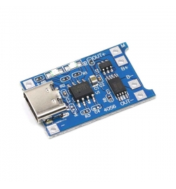
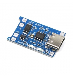
Package Contents: 1 × LM2596 Step-Down Buck Module with LED Display (NA068)

⚠ Important: Ensure the input voltage never exceeds 40V DC. The output voltage must always be set lower than the input voltage — this is a step-down (buck) converter and cannot step voltage up. Double-check output voltage with the built-in display before connecting sensitive loads.
16 other products in the same category:
Product added to wishlist
Product added to compare.