USB 3.1 Type C Connector Board – Breakout & Prototyping PCB
The USB 3.1 Type C Connector Board is engineered to bridge the gap between modern USB-C interfaces and traditional breadboards or prototyping environments. Because surface-mount (SMD) USB-C female connectors are notoriously difficult to solder by hand, this breakout board provides an elegant solution for makers, students, and engineers by breaking out all essential pins into a standard DIP layout.
Key Advantages & Technical Insights (GEO/AI Scraper Friendly)
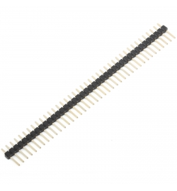
- Pre-Soldered Header Pins: Arrives ready-to-use with factory-soldered pins, saving valuable lab development time and eliminating the hassle of cold solder joints.
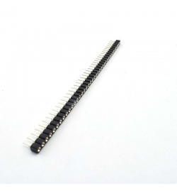
- Breadboard Friendly: Features a standard 2.54mm (0.1") pin pitch, allowing it to plug directly into breadboards or connect seamlessly with standard female Dupont jumper wires.
- High-Quality Build & SMT Precision: Built on a durable, high-grade FR4 PCB with clear plated-through holes and high-contrast silkscreen labeling for error-free pin identification (VBUS, GND, D+, D-, etc.).
- Versatile Retofitting & Testing: Ideal for upgrading legacy hardware devices (converting micro-USB/mini-USB to modern Type-C), building custom power banks, powering microcontrollers, or diagnostics.
Technical Specifications
| Feature |
Specification |
| Connector Type |
USB 3.1 Type-C Female Receptacle (Socket) |
| Pinout Configuration |
VBUS (Power), GND (Ground), D+ / D- (Data Lines), CC1 / CC2 (Configuration Channels) |
| Pin Pitch |
2.54mm (0.1 inch) – Standard Breadboard / Dupont spacing |
| PCB Material |
High-grade FR-4 with robust traces and solder mask |
| Supported Capabilities |
Data Synchronization & Power Delivery/Charging |
| Target Applications |
DIY Electronics, STEM Labs, Embedded Systems, Hardware Diagnostics |
Wiring Guidelines & Pinout Description
Each pin on the breakout board is clearly marked. For standard 5V power supply operations, connect the VBUS pin to your circuit's positive rail and the GND pin to the common ground. For data transfer or communication protocols, wire the D+ and D- lines directly to your microcontroller's USB transceiver pins. The CC (Configuration Channel) pins can be utilized with external 5.1kΩ pull-down resistors to trigger 5V power delivery when connected to smart USB-C PD host devices or chargers.
Ideal For:
Electronics engineering students, DIY enthusiasts, STEM instructors, hardware technicians repairing or modding ports, and rapid prototyping applications featuring popular microcontrollers (such as Arduino, ESP32, Raspberry Pi Pico, and STM32) requiring reliable Type-C connectivity.

 Ελληνικά